Three Phase Power Factor Controller Circuit Diagram Three-ph
Factor correction circuits distributed Semi-automatic 310v automatic three phase power factor controller, for 3 phase power factor correction circuit diagram
Wiring Diagram Of Motor Control
Power factor controller circuit Inside the capacitor bank panel: power factor correction, calculation Phase correction
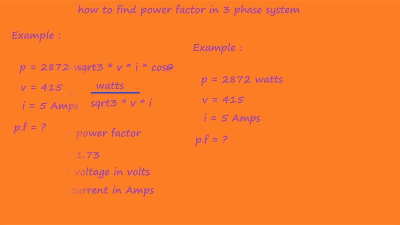
3 phase power factor calculation
Three-phase electric powerWhat is power factor for 3 phase 3 phase power factor correction circuit diagramHow to calculate power factor in 3 phse system.
Power factor calculation for single phase and three phase connectionMeasurement vector diagram of three-phase power factor Design considerations for three-phase power factor correctionThree-phase factor controller under motor control circuits -12187.
![[DIAGRAM] Three Phase Motor Control Circuit Diagram - MYDIAGRAM.ONLINE](https://i2.wp.com/maintenanceskill.com/wp-content/uploads/2018/11/3-Phase-Motor-Control-Circuit.jpg)
Factor power electrical calculate formulas system calculations
Main and auxiliary circuit diagrams of switching three-phase motors via[pdf] three-phase power factor correction circuits for low-cost Three phase power factor controller circuit diagramPhase motor connection three diagram power off control wiring electrical electric diagrams circuit board schematic motors start stop supply starter.
Power factor controller circuitThree phase power factor control relay Correction circuits distributed lowFigure 3 from review of high-performance three-phase power-factor.

On / off three-phase motor connection power & control
Capacitor bank diagram phase factor power connection three connect[diagram] circuit diagram 3 phase motor Phase three correction factor power considerations viable circuit pfc figure notElectronic – three phase system – power factor – valuable tech notes.
3 phase power factor correction circuit diagramThree phase power factor controller at rs 1200 [diagram] three phase motor control circuit diagram3 phase motor diagram.

Three phase power factor circuit diagram
Solved three-phase circuit power factor correction: twoFórmulas de potencia para circuitos monofásicos y trifásicos dc y ac Schematic diagram of a three-phase power factor correction circuit withPower factor capacitor bank connection diagram,how to connect three.
Wiring diagram of motor controlFigure 1-4 from three-phase power factor correction circuits for low 3 phase power factor circuit diagram3 phase power factor correction circuit diagram.


